Overview
The Cycle Builder is a tool that enables you to create your own custom controls and extensions in addition to the built-in cycles currently available in CIMCO Probing. The Cycle Builder has been developed to fulfil the following needs for CIMCO probing.
- Provide customers and resellers the ability to create controls and extensions not currently supported.
- Develop a tool that makes the integration and testing of cycles easier for all users.
- Provide an option that allows for testing cycles in a convenient manner without having to update to the latest version of CIMCO Probing each time to the get the most recent changes.
The Cycle Builder creates a standalone configuration folder containing all the required information and files for the set of custom cycles. Once a new custom control or extension has been created, the cycles can be transfered to other users by simply copying the folder to their PC.
Getting started
This section provides an overview of the basic use of the Cycle Builder. To use the Cycle Builder effectively, you need to understand the desired cycles well. You should have the cycle documentation ready before you start the implementation.
If you are using the cycle builder for the first time, you should check out one of the examples to see how it works. You can find examples of using the cycle builder in the CIMCO probing content folder. The following steps describe the general process of using the Cycle Builder.
- Create a new custom control or extension
- Configure base settings
- Add the desired cycles
- Preview cycle and validate NC output
- Add control or extension id to CIMCO Probing XML section.
- Use cycles in Mastercam
Hints
This section introduces some useful features and summarizes the main aspects of using the Cycle Builder.
Creating new custom controls or extensions
- Name must be unique. This is used for generating the configuration folder and the id required in the CIMCO Probing XML section for loading the cycles.
- A new custom control or extension can be created by making a copy of an existing.
- A control or extension configuration folder can be copied from the CIMCO Probing content folder to you local content folder. This enables you to access and use the example files.
Creating cycles
- Cycles must be added to the correct category based on the use case and configuration of the cycle.
- Creating one initial cycle with all the required information is the recommended procedure as these settings can then be copied to subsequent cycles.
- The selected toolpath type should match the motion of the desired cycle.
Creating parameters
- All parameter ids must be unique so they can be referenced.
- Required parameters are automatically added based on the selected toolpath type.
- Changes to common parameters will be added to all cycles containing that parameter.
NC output
- The cycle preview is a direct representation of how the cycle will look when used and also shows how the NC output will be outputted when posting.
- The order of cycle parameters matches the order in which parameters are outputted.
Value output formatting
- Right-clicking the mouse in the output field displays a pop-up menu where parameter ids and custom values can be accessed.
- Parameters and custom values can be accessed by formatting the output like so [{id}]
- Adding $ to the formatting like so [${id}] will use the output formatting for that parameter. This makes it possible to recursively reference parameters.
- Adding # to the formatting like so [#{id}] will look at the state of the parameter. If it is enabled, it is equal to 1 and if disabled it is equal to 0.
Using Conditions
- Value formatting can be used when adding condition.
- Checking if a parameter is enabled can be done in the following way: [# {id} ]= [1]
General information
- Hovering over any input field will display a tooltip.
- Right-clicking input fields will display a quick access menu (if one is available for that input type).
- Parameters, Moves and Manual entries will be outputted in the order they are listed in the Cycle Builder.
- For the configuration file to be updated, the control/extension must be saved by clicking on the save button under Base Settings.
- Under the content folder for CIMCO Probing, a selection of generic images can be found. Copy these to the current control/extension configuration folder for accessing, if needed.
- Under the content folder a translation file containing generic strings can be found. Copy this to the control/extension configuration folder for accessing.
Creating a custom extension or control
This section covers the process of creating a custom extension or control and how to configure the Base Settings.
Difference between extension and controls
A control is a set of cycles from a specific manufacturer, such as Heidenhain or Siemens. An extension lets you add new cycles to an existing Control. For example, you can extend the default Heidenhain Control, which has all the main cycles, with modified or unavailable Heidenhain cycles.
Base settings configuration
Naming
The name of the custom control or extension has the following requirements.
- The name must be unique (must not match any previously created)
- Only normal characters are allowed (Only ASCII, no special characters allowed)
- Must not contain the name of currently supported controls, including:
- brother
- fanuc
- heidenhain
- haas
- makino
- mazak
- millplus
- mitsubishi
- okuma
- siemens
- doosan
- matsuura
- kineticcontrol
Measurement Variables
The Min and Max measurement variables define the range of the variables used when outputting selected measurement results.
 Measurement Variables.
NC output formatting
Macro Call
Text inserted in the Macro Call field will be outputted in front on all cycle output lines for that control/extension.
Probe On
Text inserted in the Probe On field will be outputted when the Probe On command is called internally. This is the start of a probing operation in Mastercam. The Probe On command can be overwritten by using the Probe On field in the CIMCO Probing XML section in the post processor.
Probe Off
Text inserted in the Probe Off field will be outputted when the probe off command is called internally. This is the end of a probing operation in Mastercam. The Probe Off command can be overwritten by using the Probe Off field in the CIMCO Probing XML section in the post processor.
 Macro call, Probe On and Probe Off.
Multi-line
The Multi-line option controls if cycle parameters are outputted on one line or multiple lines in the NC output.
Spacing
The Spacing option controls if cycle parameters are outputted with spaces or not. If the option is selected, a space is automatic inserted between outputted parameters.
Remove multiple spaces
The Remove multiple spaces option removes unnecessary spaces from NC output lines. This is mostly a preference option to make the NC output look more structured, without having to systematically go thought all outputs and make sure that the formatting is consistent. This option should be used if the added spaces in the formatting is not deliberately added.
 Remove multiple spaces.
Validation
Validation must be configured when creating a control. When creating an extension, this will get the Validation configuration from the parent control (the control being extended).
The Validation configuration is used when using the if/then conditions in a cycle. If the control does not support if/then conditions, this section can be ignored. Just disable the if/then condition feature under the cycle settings.
The Validation section for the Base Setting is configured when creating a new custom control. Input fields ending with "Comment" must be adjusted to match the expected comment output on the machine. Most machines use parenthesis, but it may vary.
Goto label
Text inserted in the Goto label field will be outputted before an NC line number label. The number labels in the final NC output, tells the machine which lines to jump to when running the program.
Use sequence number on goto label
The Use sequence number on goto label option, if enabled, will output the next sequence number on a Goto line. This option should be disabled if the control is using sequence numbers as the Goto label.
 Validation.
Cycle generation
Always output required parameters
The Always output required parameters option, if enabled, will set the always output parameter option to "Yes" for required parameters for new cycles. This should only be enabled if all parameters should be outputted as default.
Creating cycles
Cycle categories
The available categories are Alignment, Datum and Inspection.
- The Alignment category is used for cycles that can align the rotational axis on the machine.
- The Datum category is used for cycles that can set the work offset on the machine.
- The Inspection category should be used for cycles that can measure a specific feature.
The main difference between the cycle categories are the following. Based on the category selected, different task information is passed on to the post processor for correctly handling the NC output generation. The task information passed to the post processor should be correctly handled in the probing effect section that handles the effect of probing cycles.
- Using the Datum category will update the prb_datum_updated variable in the post. The goal is to invalidate the work offset variable if current work offset is updated. This will output the work offset again given that the post processor is configured correctly.
- Using the Alignment category will update the prb_rotaxis_updated variable in the post. The goal is to invalidate the current rotary axis position. This will output the rotary axis position again given that the post processor is configured correctly.
- No probing effect postblock needs to be configured in the post processor when using an inspection cycle.
Generic toolpath types
When creating a new cycle, the toolpath type option should match the motion of the desired cycle.
The currently supported toolpaths are the following:
- Point One Axis - Geometry selection 1 point
- Point At Angle - Geometry selection 1 point
- Edge One Axis - Geometry selection 2 points
- Width Inside - Geometry selection 2 lines or 4 points
- Width Outside - Geometry selection 2 lines or 4 points
- Width Inside At Angle - Geometry selection 2 lines or 4 points
- Width Outside At Angle - Geometry selection 2 lines or 4 points
- Corner Inside - Geometry selection 2 lines
- Corner Outside - Geometry selection 2 lines
- Rectangle Inside - Geometry selection 4 lines or chain
- Rectangle Outside - Geometry selection 4 lines or chain
- Diameter Inside - Geometry selection 1 circle
- Diameter Outside - Geometry selection 1 circle
- Plane - Geometry selection 3 points
- No toolpath - No Geometry selection option
Based on the toolpath type selected, different geometry options can be selected in Mastercam when using the cycle. Diameter Inside makes is possible to select a circle, Point One axis a point and so on. The toolpath type controls the cycle motion displayed in Mastercam and automatically pulls the required geometry information form the selection and inserts it into the parameter field.
This makes it user-friendly and more intuitive to use, but is at its core not necessary. A Point One axis toolpath can be configured to match a Diameter Inside toolpath. The diameter for the hole just needs to be manually added. It would not look correct in Mastercam, but the NC output would match the macro call needed on the machine.
The Cycle Builder gives the user the freedom to fully format the NC output for a probing operation as they desired.
Settings
This section covers the base configuration of a cycle.
Naming
Name
Text inserted in the Name field will be displayed in the cycle selection menu.
Description
Text inserted in the Description field will be displayed when hovering over a cycle in the cycle selection menu. Right-clicking on this input field will display a translation list, if any translations has been added to the translation file in the configuration folder.
A generic translation file is located in the content folder. This file can be copied to the configuration folder for the control/extension and used as a baseline.
The control/extension must be reloaded to get the latest changes made to the translation file. The translation file loads once, when the control/extension is opened.
Display Image
This should contain the path to an image in configuration folder. If the path is valid, the image will be displayed when hovering over a cycle in the cycle selection menu. Right-clicking on the input field will display an image list if any images has been added to the image folder in the configuration folder.
A list of generic images can be located in the CIMCO Probing content folder. These images can be copied to the configuration image folder and used as a baseline. It is also possible to use custom images. They just need to be added to the image folder as well.
Images can be added to the image folder during the configuration process and loads at runtime.
Output Start
Text inserted in the Output start field will be outputted as the first part of the cycle output. The cycle macro name should be added to this line for most controls/extensions
Output End
Text inserted in the Output end field will be outputted as the final part of the cycle output. This field can be used for a cycle comment or if the cycle requires some specific formatting in the end after the cycle parameters has been outputted.
Cycle Options
Active Cycle
The Active Cycle option, if enabled, will display the cycle as an option in the cycle selection menu. If disabled, the cycle will not be able to be used. This allows for the option to use a subset of cycles and work on others that has not yet been fully completed.
Meas result
The Meas result option, if enabled, will enable the Measuring result feature for the cycle.
Probe On / off
The Probe On/Off option, if enabled, will enable the Probe On/Off feature for the cycle.
If/Then conditions
The If/Then conditions option, if selected, will enable the If/Then conditions feature for the cycle.
Tool list
The Tool list option, if selected, will enable the tool list feature for the cycle.
Auto tool list offset
The Auto tool list offset, if selected, will enable the automatically tool offset feature when using re-machining.
Validation
The Validation input fields are used for If/Then conditions. The fields must be configured to match the correct cycle measurement values stored on the machine when running the cycle.
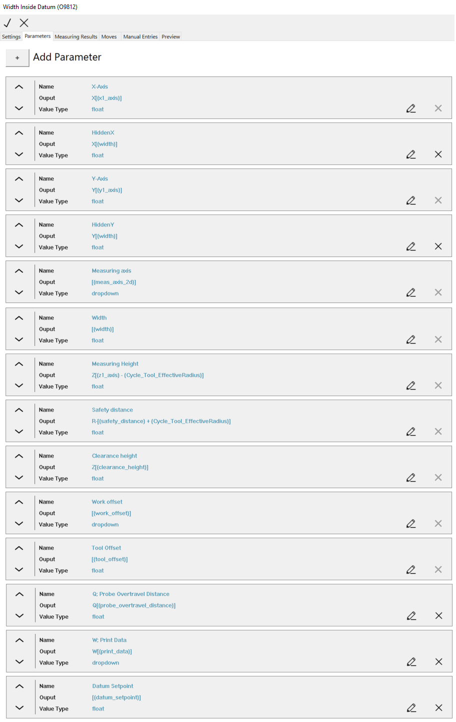
Parameters
Given the selected toolpath option type, a set of required parameters are added to the cycle. These parameters are required for controlling the internal logic of the cycle and retrieving the needed data when using it. The required parameters can not be deleted and if they are missing from the created configuration file the cycle will not work.
Adding new parameters
Using the Add parameter option, a new or existing parameter can be added to a cycle. Adding an exising parameter to a cycle will create a copy of the selected parameter and add it to the cycle as the last parameter.
Sorting parameters
The order of the parameters are tied to the order they are outputted and displayed in the UI. Changing the order of the parameters listed will affect the order in which they are outputted.
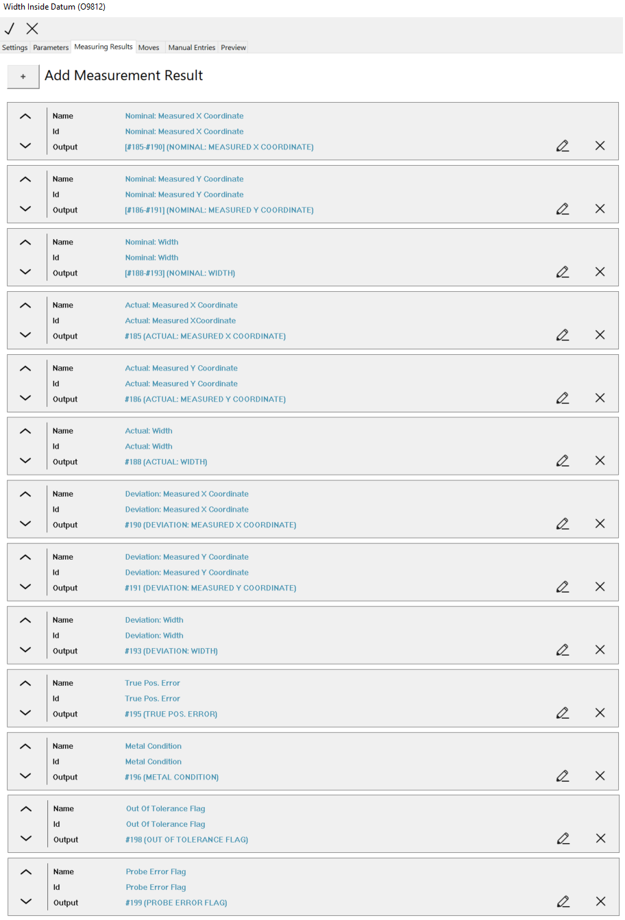
Measurement result
Measurement results are shown in the Measurement result list if the Meas result option is enabled for the cycle.
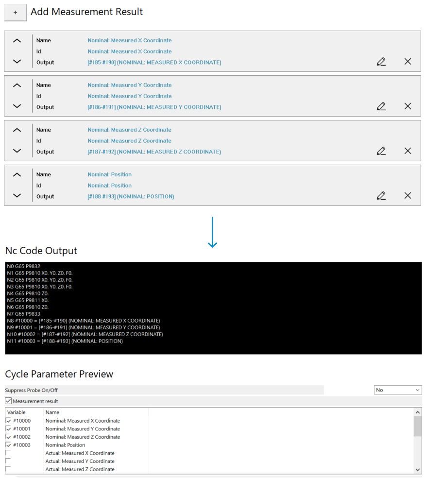 Measurement result.
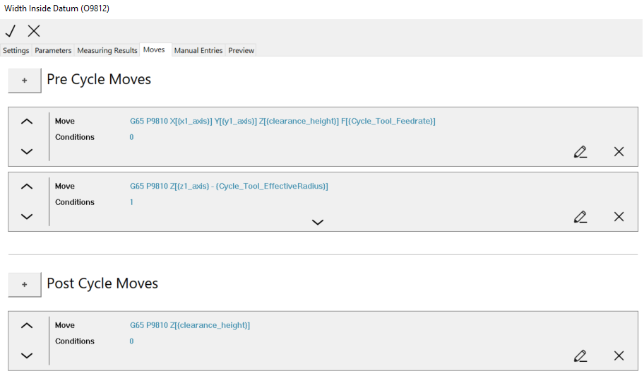
Moves
Moves are added before and after the cycle output. Moves should be used to pre-position the probe before outputting the cycle and moving the probe back to clearing height.
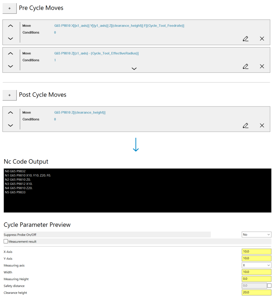 Pre and post cycle moves.
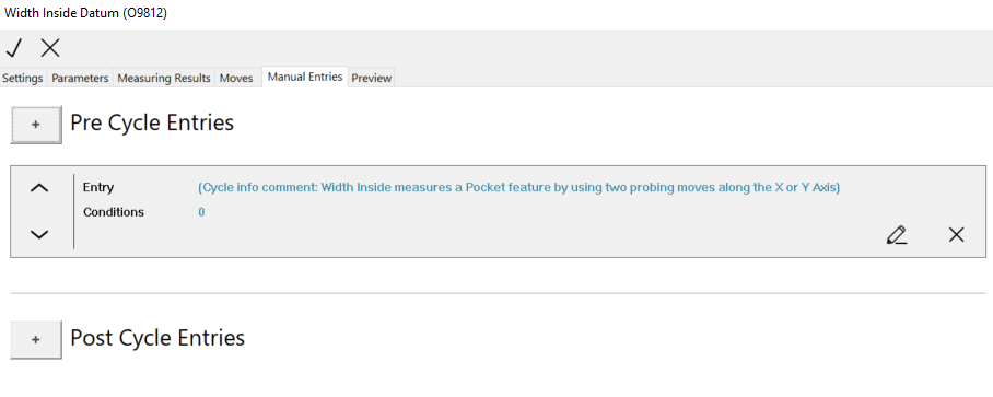
Manual Entry
Manual entries are added before and after the cycle moves and the probe on and off command is outputted. The use case for the manual entries can vary a lot, but it is intended to be used for adding comments to cycles and any manual entry that would have been added using the manual entry operation in Mastercam.
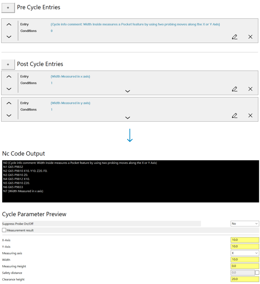 Pre and post cycle entries.
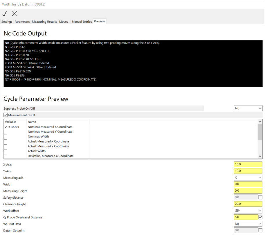
Cycle Preview
The Cycle Preview can be used to preview and test the cycle during the configuration process. The preview will display a compiled representation of how the cycle will look when used and the associated NC output when posting in Mastercam.
The cycle must be configured so the preview shows the expected result.
Creating parameters
Cycle parameters are the building blocks for generating the cycle output. Think of a parameter as a data container. This data can be accessed, formatted, combined and outputted in multiple different ways.
Naming
Name
Text inserted in the Name field will be outputted as the parameter name when using the cycle.
Id
The Id of the parameter must be unique. The id is used to access the data of the parameter.
Output
Text inserted in the Output field will determine how the parameter is formatted and outputted. Look in the Value formatting section for a more details.
Tool tip Description
Text inserted in the Description field will be displayed when hovering over the parameter. Right-clicking on the input field will display a translation list, if any translations has been added to the translation file in the configuration folder.
Image
Sets the path to an image in the configuration folder. Given a valid path, the image will be displayed when hovering over the parameter. Right-clicking on the input field will display an image list, if any images has been added to the image folder in the configuration folder.
Common parameter
The Common parameter option, if selected, will update all cycles containing the same parameter with the given id. If a parameter should be universal across all cycles, this should be enabled.
Display
Always output parameter
The Always output parameter, if selected, will always output the parameter given that the parameter is enabled.
Output only when formatted
The Output only when formatted option, if selected, will only output the parameter if it is referenced elsewhere. The parameter itself will not be outputted. A more detailed explanation can be found in the Value output formatting section.
All conditions must be valid
The All conditions must be valid option, if selected, will only output the parameter if all conditions are valid. If disabled, only one condition must be valid for the parameter to be outputted.
The intended use for the conditions is to disable the Always output parameter option and add conditions for when the parameter should be outputted.
Value
State
The State option controls the state of the parameter.
- Default: Displayed normally
- Optional: The parameter will be optional and enabled by default
- Optional Disabled: The parameter will be optional and disabled by default
- Hidden: The parameter will be hidden in the UI, but will still be outputted if the display options and conditions for outputting the parameter are valid.
Creating a hidden parameter to store and output a value is a great way to achieve a desired cycle output.
Custom Value formatting
In most cases this is not used. This is an advanced option for customizing the value formatting. If this option is empty the default value type formatting for the parameter type is used. This means that an Integer will be formatted as an Integer, a Float as a Float and a String as a String.
- Integer default formatting: Round any Float value to closest Integer 1.2 -> 1 etc
- Float default formatting: Round any Float to fourth decimal number and remove any trailing zeros. A formatted Float will always be outputted with a period. 1.2245274567 -> 1.2245, 1.000000000 -> 1. etc.
- String default formatting: Strings will be outputted exactly as defined and no additional formatting is used. Using string parameters can be a way for achieving a specific output that can not be predefined as a dropdown option.
If a custom value formatting is added, the parameter value can not be used in a calculation. The following pattern can be used for formatting the different value types.
- Integer: %d
- Float: %f
- String: %s
Example: This option is useful if you want to output an Integer with added zeros. If you have a parameter value with the Integer type such as 1, 10 or 100 and you want to output it as 001 010 100, the formatting used for this would be %03d.
When formatting is applied, the value of the parameter is processed as a string. It is possible to add text to the custom formatting input field, but is highly incentivized not to do this. Text should be added as part of the output field.
Type
The parameter can have the following types.
- Integer
- Float
- String
- Dropdown: The Dropdown can then contain either Integers, Floats or Strings.
Based on the selected type, only that value type can be inserted in the parameter field or selected.
It the parameter has an Integer or Float type, the value can be used in a calculation. Parameters containing a String will be skipped when the parameter is evaluated. See the Value output formatting for more details.
Default value
The Default value will be added as the default when using the cycle. If the Dropdown value type is used, the default value must match one of the added options for the dropdown. This will then be selected as the default option.
Value output formatting
The Value formatting binds it all together and works in the following way: An output string, containing a set of brackets [], will be evaluated. Everything inside the bracket will be evaluated. A parameter or pre-defined value can be referenced by using a set of curly brackets {}. In an output formatted with [{id}], the brackets and curly brackets will be replaced with the value of the parameter.
If an invalid id is added inside the curly brackets, the evaluation will result in a empty output. When formatting an output, make sure that the brackets and curly brackets match. It will not work if they are misaligned.
Formatting options
Get values
Accessing the value of a parameter can be done with [{id}]. Outputting the value of the X-axis parameter would look like X[{x_axis}]. The [{x_axis}] would pull the value for the parameter with the x_axis id and output it as X5 provided the value of the x_axis parameter is 5 in this case.
This can be extended with multiple sections that must be evaluated on one output line. This would be the case when outputting a move and could look like G00 X[{x_axis}] Y[{y_axis}] Z[{z_axis}]. This will be compiled as G00 X5 Y5 Z5 given the value of all the parameters are 5 in this case.
Having [{id}] pulls the value of the given parameter. The output line for a custom parameter could look like CustomValue1[{custom_1}] CustomValue2[{custom_2}] CustomValue3[{custom_3}]. This implies that the parameter can be reference in other parameters.
All input fields that allows for value output formatting can pull data for parameter or pre defined values.
Reference parameter
Having [{id}] will pull the value for a parameter, but is also possible to reference the output formatting for the specific parameter like so [${id}] by adding a $ in front of the curly brackets.
Given a output line that looks like the following Data:[${otherdata}]. When the output line is evaluated the reference to the otherdata parameter is identified. The otherdata output formatting look like the following (First=[${somedata_1}],Second=[${somedata_2}]). This would be outputted as Data:(First=5,Second=5) given that the value of the parameters somedata_1 and somedata_2 are 5 in this case.
This is a recursive process which means that you can reference a parameter that also reference a parameter and so on. The can result is a infinite loop so the maximum number of recursions is limited to 3.
Get state of parameter
Having [# {id}] will pull the state for a parameter. If enabled, this is equal to 1 and if disabled equal to 0. This is useful tool for controlling when to output parameters.
If a custom parameter has been created - lets call it C. Parameters with the name J and K should only be outputted when Parameter C is enabled. Adding a condition to J and K that checks the state of C would solve this problem.
A more practical application of this feature would be to check if the safety distance is enabled or disabled. This would change how some pre-position moves and certain parameters should be outputted.
Using math
It is possible to perform math operations as part of the value output formatting. Everything inside a set of brackets [] is by default processed as a math operation. If all values, when evaluated, has the Integer or Float type, and no custom formatting has been added, the output will be parsed and calculated.
Given an output line that looks like Result=[{somedata_1}+{somedata_2}]. This would be outputted as Result=10 given that the value of the parameters somedata_1 and somedata_2 are 5 in this case.
The math operations follow the PEMDAS standard. Parentheses, Exponents, Multiplication, and Division (from left to right), Addition and Subtraction (from left to right). It is possible to use the following math operations:
- Addition: value + value = value
- Subtraction: value - value = value
- Multiplication: value * value = value
- Division: value / value = value
- Sine: S(value) = value
- Cosine: C(value) = value
- Tangent: T(value) = value
- Arc Sine: s(value) = value
- Arc Cosine: c(value) = value
- Arc Tangent: t(value) = value
- Square root: q(value) = value
- Power of two: p(value) = value
- Absolute value: a(value) = value
- Using Parentheses: (value + value) = value, (value - value) = value etc.
Based on the math operation restriction, the way a negative number is outputted is in the following way: [0-1] or [0-{id}]. This will output -1 or flip the value of the parameter to a negative number.
The values and operations must match in the output line. Having a mismatch between values and operations will result in an incorrect calculation or error warning that can not be ignored.
It is recommended not to use the math division operation, if possible, because division by zero can easily occur, which will result in an invalid calculation. If the goal is to divide a value by two, the better option is to multiply the value by a half like value * 0.5.
Example
The values of the parameters and custom values included in the examples are defined as the following:
- {somedata_1} = 5
- {somedata_2} = 4
- {pi} = 3.1415...
- {cycle_tool_radius} = 10
- [{somedata_1} + {somedata_1}] = 5 + 5 = 10
- [{somedata_1} + {somedata_2}] = 5 + 4 = 9
- [{somedata_1} - {somedata_1}] = 5 - 5 = 0
- [{somedata_1} - {somedata_2}] = 5 - 4 = 1
- [{somedata_1} + {somedata_1} 4] = 5 + 5 4 = 25
- [( {somedata_1} + {somedata_1} ) 4] = (5 + 5) 4 = 40
- [( {somedata_1} + {somedata_1} ) / 2] = (5 + 5) / 2 = 5
- [( {somedata_1} + {somedata_1} ) 0.5] = (5 + 5) 0.5 = 5
- [{pi} p({cycle_tool_radius})] = 3.1415 p(10) = 3.1415 * 100 = 314.15
XML configuration in post processor
To access the cycles in Mastercam, the ID for the control or extension needs to be added to the XML configuration in the post processor. Control
Add the control ID to the ControlName Input field in the XML configuration in the post.
 Probing XML configuration - Control
Extension
Add the extension ID to the Custom_Extensions section in the XML configuration in the post processor. Adding multiple extensions is allowed.
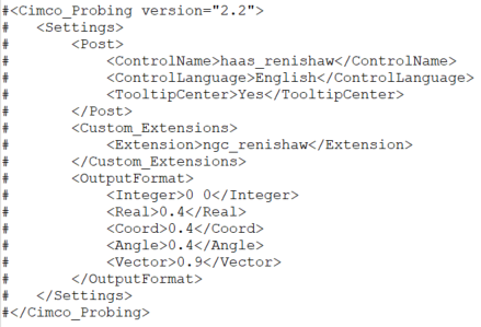 Probing XML configuration - Extension
Step by step guide: A practical example
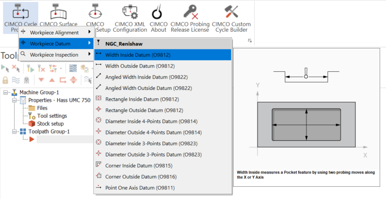
Open Cycle Builder
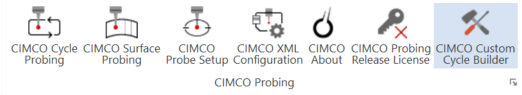 Cycle Builder Menu.
Create new control
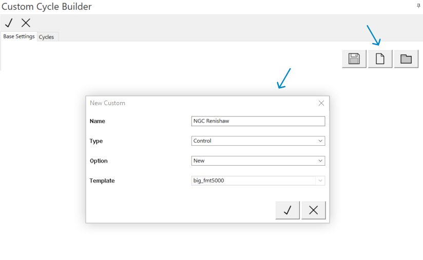 Create new control.
Add base settings
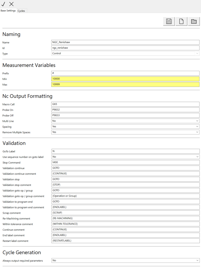 Add base settings.
Navigate to cycle tab
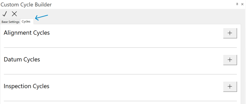 Navigate to cycle tab.
Add needed cycles
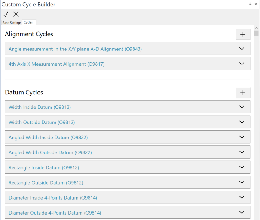 Add needed cycles.
Edit cycle
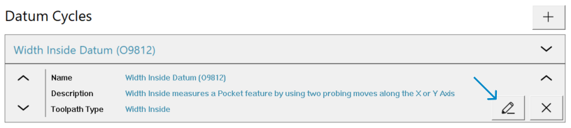 Edit cycle.
Add cycle settings
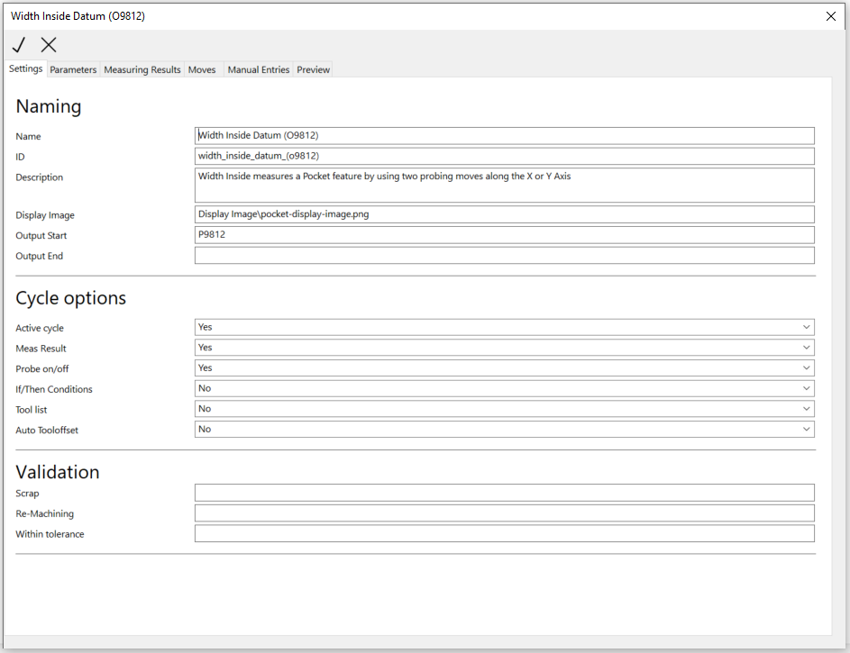 Add cycle settings.
Add cycle parameters and change output order
 Add cycle parameters.
Add measurement results
 Add measurement results.
Add cycle moves
 Add cycle moves.
Add cycle entries
 Add cycle entries.
Preview cycle and make sure that everything is correct
 Preview cycle.
Add ID to CIMCO Probing XML configuration section in post
Add ID to Cimco Probing XML configuration.
Use cycles in Mastercam
 Cycle Selection Menu.