Introduction
This section describes the software user interface and the functionality that it provides.
Toolbar icons
Icons can be added to any toolbar of your choice (See "Mastercam toolbar icons").
![]()
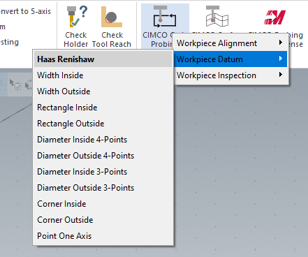
Cycle probing
Cycle probing is for general feature-based measurement cycles, which are listed in categories for their specific application.
Surface probing
Surface geometry can be inspected by using Surface probing.
Release license
A floating license is reserved while the Mastercam session is active, click the 'Release license' icon to make the license available to other users on the network.
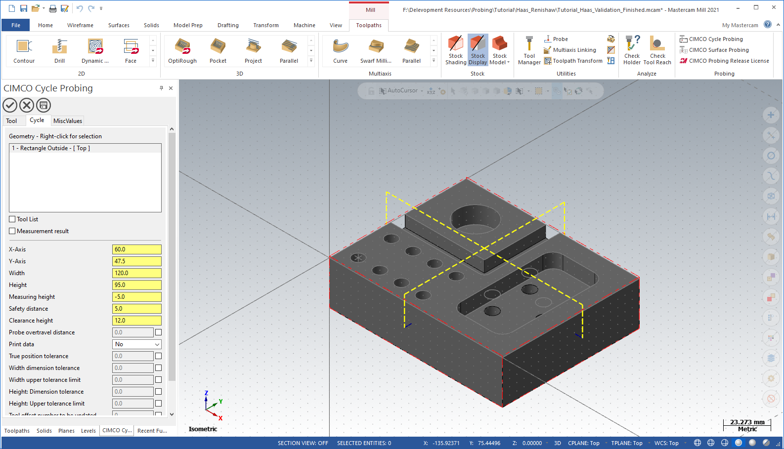
Operation panel
After selecting a probing cycle from either the Cycle probing or Surface probing menu, the operation user interface will spawn in the function panel, allowing free movement and rotation of the part, and switching to other panels, without obstructing the view.
Buttons
The operation panel has three main buttons, placed at the top:
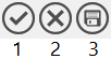
- Accept
When clicking the accept button, the operation/cycle settings are saved to the operation and toolpath is saved to the Mastercam NCI. If an existing operation is modified, the operation will be marked 'dirty', needing to be regenerated for the Mastercam NCI to be updated. In case of invalid operation/cycle settings an error will be shown upon clicking the accept button or when regenerating the operation.
- Cancel
Any changes made to the operation will be discarded when clicking the cancel button.
- Save defaults
When clicking the save button, the current cycle parameter values are saved as default values for the selected cycle, and will be used as initial values next time an operation is created with the selected cycle.
Tabs
Operation/cycle parameters are located on multiple tabs, see the specific sections for more information.
Tool
Tool, holder and other settings related to the operation is specified on the tool tab.
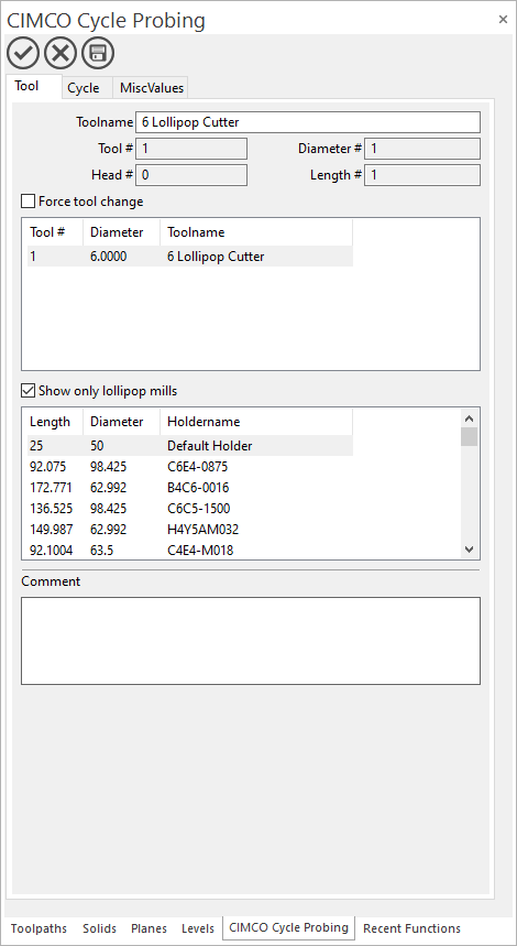
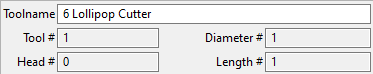
Tool data
The tool data fields show the parameters of the selected tool, the fields are read-only, right-click in the tool list and select 'Edit tool' to modify the tool data.
Force tool change
When enabled the post-processor will output a tool change before this operation, even when the previous operation is using the same tool.
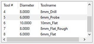
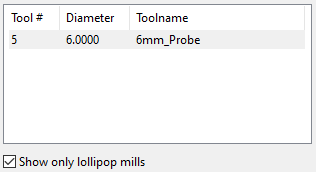
Tool list
Tools in the active machine group are shown in the tool list. Right-click for options.
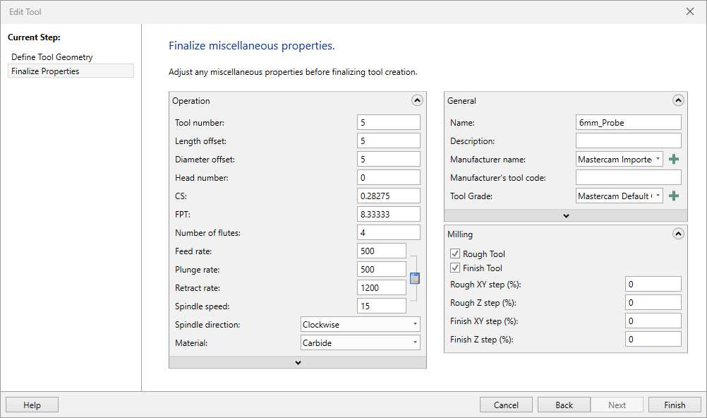
Edit tool
Launches the tool wizard to edit the selected tool.
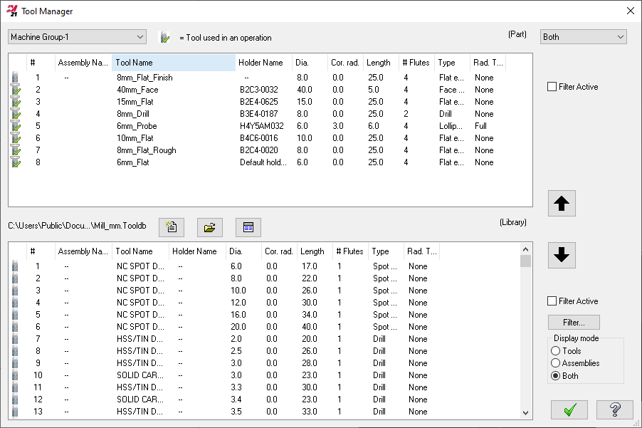
Tool Manager
Launched the tool manager, where tools can be created and/or imported from tool libraries.
Show only lollipop mills
When enabled only lollipop mill tools are shown in the tool list.
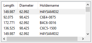
Holder list
Holders in the active tool library are shown in the holder list. Right-click for options.
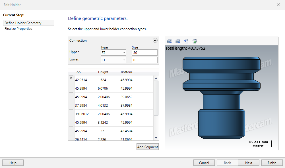
Edit holder
Launches the holder wizard to edit the selected holder.
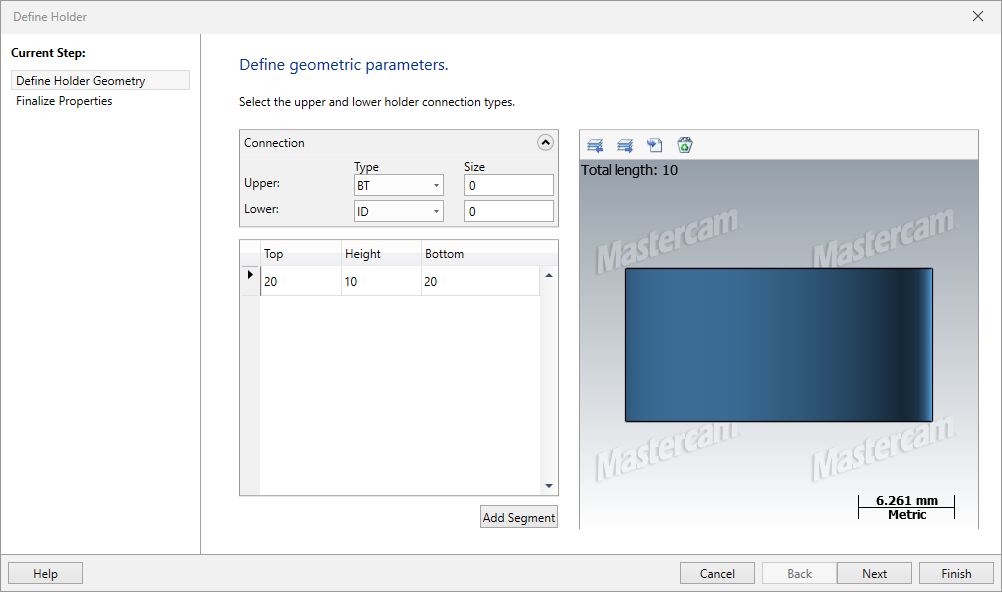
New holder
Launches the holder wizard to create a new holder.
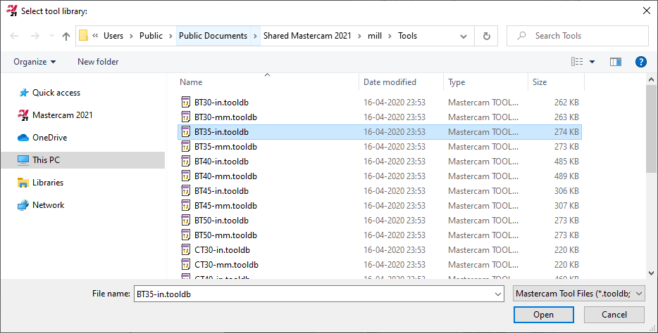
Open library
Launches the file explorer to select a library to open, the holders in the selected library will be shown in the holder list.
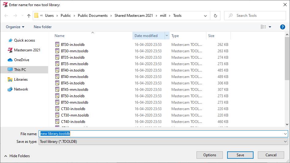
Save library
Launches the file explorer to save the library.
Operation comment
Write an operation comment to be included in the NC code.
Cycle parameters
Cycle parameters, and other settings related to a probing cycle, are specified on the cycle tab.
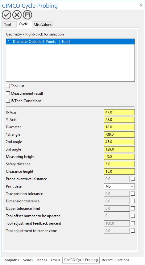
Geometry/Cycle list
Select geometry, manage cycles and adjust settings in the geometry list. Right-click for options.
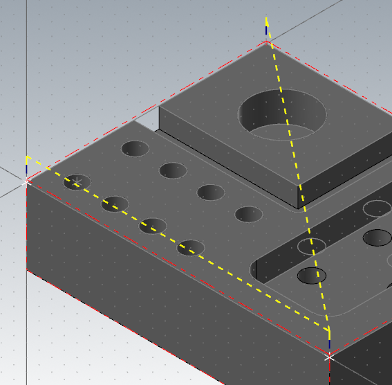
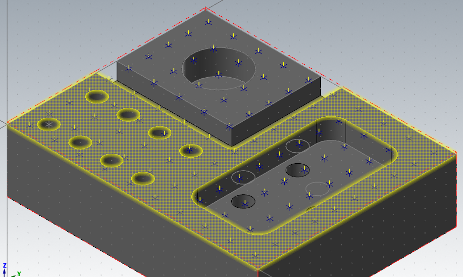
Geometry selection
Geometry selection options depends on the selected probing cycle. Geometry can be continuously selected, with each complete selection a copy of the selected cycle will be added to the geometry list, copying parameters from previous cycle and applying the select geometry to the cycle parameters. The measurement cycle types handles plane selection differently, some derives the plane from the selected geometry, others require manual plane selection.
Point measurement
Point measurement cycles have the option to select point geometry. A new cycle will be added to the geometry list with each selected point.
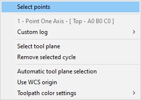
Automatic tool plane selection:
- Enabled
The active tool plane is used.
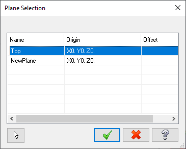
- Disabled
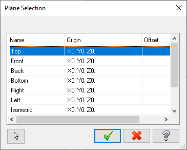
Select an existing plane from the Plane Selection window or create a new plane by selecting 'NewPlane'. Accept to continue.
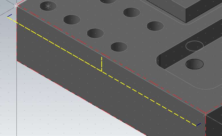
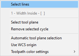
Edge measurement
Edge measurement cycles have the option to select line and point geometry, using the 'Select points' option. A new cycle will be added to the geometry list with each selected line/pair of points.
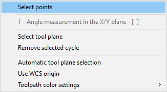
When selecting line geometry, an offset is applied to contain the measurements within the extend of the line.
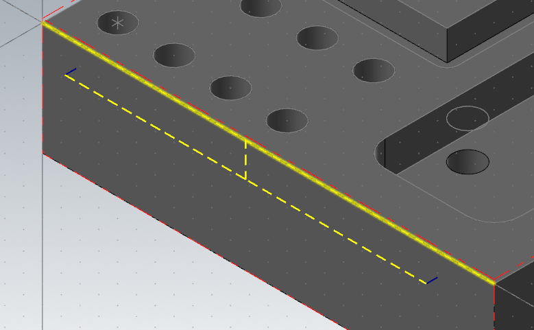
When selecting point geometry, no offset is applied as the selected points are considered target locations for the measurements.
Automatic tool plane selection:
- Enabled
The active tool plane is used.
- Disabled
Select an existing plane from the Plane Selection window or create a new plane by selecting 'NewPlane'. Accept to continue.
Ridge measurement
Ridge measurement cycles have the option to select line geometry. A new cycle will be added to the geometry list with each selected pair of lines.
Automatic tool plane selection:
- Enabled
An exiting tool plane is used if the Z-axis of the plane is perpendicular to the selection and the X- or Y-Axis is parallel to the selection, preferring the active tool plane, otherwise a new plane is created.
- Disabled
Select an existing plane from the Plane Selection window or create a new plane by selecting 'NewPlane'. Accept to continue.
Corner measurement
Corner measurement cycles have the option to select line geometry. A new cycle will be added to the geometry list with each selected pair of lines.
Automatic tool plane selection:
- Enabled
An exiting tool plane is used if the Z-axis of the plane is perpendicular to the selection and the X- & Y-Axes are parallel to the selection, preferring the active tool plane, otherwise a new plane is created.
- Disabled
Select an existing plane from the Plane Selection window or create a new plane by selecting 'NewPlane'. Accept to continue.
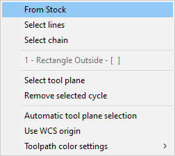
Rectangle measurement
Rectangle measurement cycles have the option to select line geometry or a geometry chain, and to use stock dimensions. A new cycle will be added to the geometry list with each four lines when using the 'Select lines' option or with each chain or stock selection.
Automatic tool plane selection:
- Enabled
An exiting tool plane is used if the Z-axis of the plane is perpendicular to the selection and the X- & Y-Axes are parallel to the selection, preferring the active tool plane, otherwise a new plane is created.
- Disabled
Select an existing plane from the Plane Selection window or create a new plane by selecting 'NewPlane'. Accept to continue.
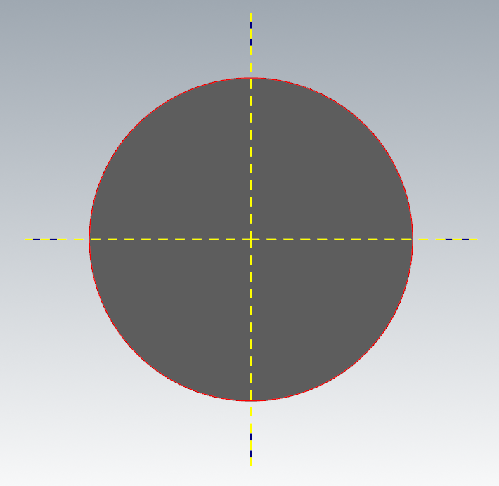
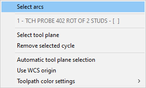
Circle measurement
Circle measurement cycles have the option to select arc geometry. A new cycle will be added to the geometry list with each selected arc.
Measurement cycles that supports step angle:
When selecting a full arc, the starting point is considered first measurement location and the step angle is configured to measure each quadrant of the arc.
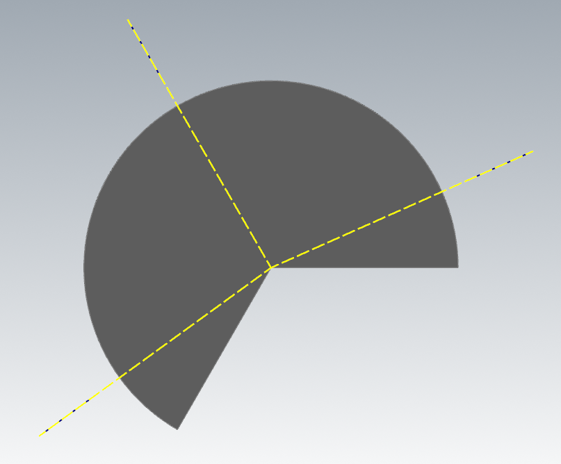
When selecting a partial arc, the start and step angle is configured to contain the measurements within the extend of the arc.
Automatic tool plane selection:
- Enabled
An exiting tool plane is used if the Z-axis of the plane is perpendicular to the selection, preferring the active tool plane, otherwise a new plane is created.
- Disabled
Select an existing plane from the Plane Selection window or create a new plane by selecting 'NewPlane'. Accept to continue.
Bolt hole measurement
Bolt hole measurement cycles have the option to select arc geometry. A new cycle will be added to the geometry list with each 3rd selected arc.
Automatic tool plane selection:
- Enabled
An exiting tool plane is used if the Z-axis of the plane is perpendicular to the selection, preferring the active tool plane, otherwise a new plane is created.
- Disabled
Select an existing plane from the Plane Selection window or create a new plane by selecting 'NewPlane'. Accept to continue.
Circle pair measurement
Circle pair measurement cycles have the option to select arc geometry. A new cycle will be added to the geometry list with each selected pair of arcs.
Automatic tool plane selection:
- Enabled
An exiting tool plane is used if the Z-axis of the plane is perpendicular to the selection, preferring the active tool plane, otherwise a new plane is created.
- Disabled
Select an existing plane from the Plane Selection window or create a new plane by selecting 'NewPlane'. Accept to continue.
Plane measurement
Plane measurement cycles have the option to select point geometry and surface points. A new cycle will be added to the geometry list with each 3rd selected point.
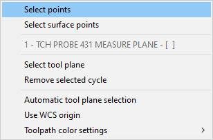
When selecting point geometry, select three points to complete plane geometry selection, each selected point is considered target measurement location.
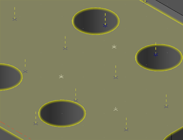
When selecting surface points, select a target surface to bring up surface point selection.
Use the surface UV controls to adjust point distribution.
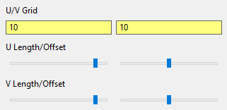
Or select any point directly on the surface.
Automatic tool plane selection:
- Enabled
An exiting tool plane is used if the Z-axis of the plane is perpendicular to the selection and the X- & Y-Axes are parallel to the selection, preferring the active tool plane, otherwise a new plane is created.
- Disabled
Select an existing plane from the Plane Selection window or create a new plane by selecting 'NewPlane'. Accept to continue.
Surface point measurement
Surface point measurement cycles have the option to select surface points. A new cycle will be added to the geometry list with each selected point.
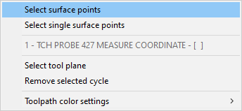
Select target surface(s) to bring up surface point selection.
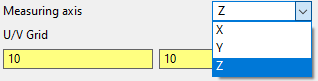
Specify measuring axis.
Use the surface UV controls to adjust point distribution.
Or select any point directly on the surface.
Automatic tool plane selection is always enabled for surface point selection.
An exiting tool plane is used if the Z-axis of the plane is perpendicular to the selection, preferring the active tool plane, otherwise a new plane is created.
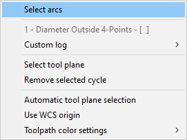
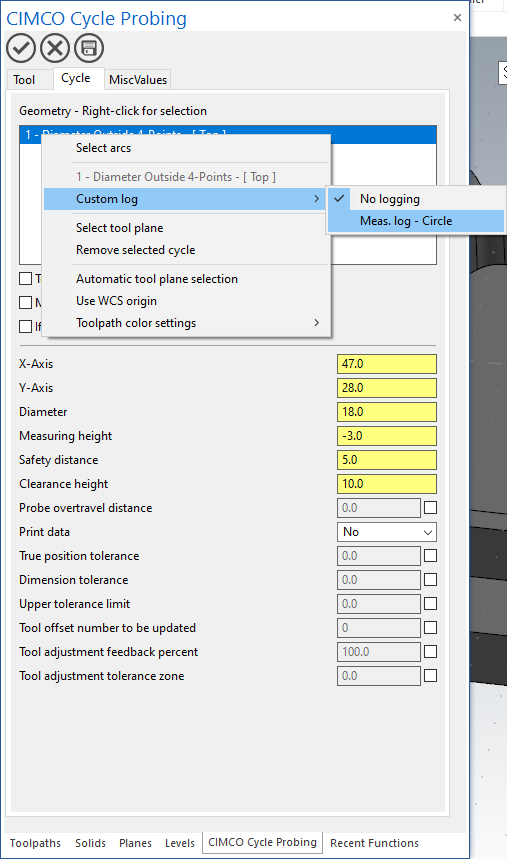
Custom log
Custom logs that are available for the selected cycle are listed in the 'Custom log' sub-menu. The sub-menu is only available if any custom logs are defined for the cycle.
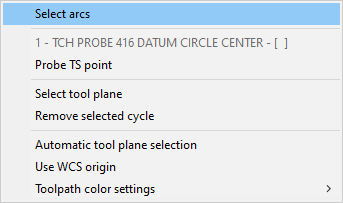
Probe TS
Select the Probe TS option to select a point geometry. The Probe TS option is only available for cycles that supports this feature.
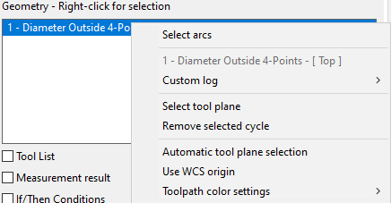
Re-select tool plane
Select this option to re-select tool plane based on the selected geometry.
Removing cycle(s)
Remove the selected cycle/all cycles using 'Remove cycle' / 'Remove all cycles'.
Settings
- Automatic tool plane selection
When this option is enabled, the software will automatically select a tool plane upon geometry selection.
- Use WCS origin
When this option is enabled, the software will filter/select tool planes that have the origin in the same location as the active WCS.
- Toolpath color settings
Adjust the colors for toolpath preview.
Tool list
The selected tool is used as target for tool dimension correction.
Measurement results
Store the measurement result in machine variables.
If/Then conditions
Types
Measurement validation includes three conditions, you can control the program flow by specifying an action for the individual contions.
- Scrap
The deviation is larger than the upper tolerance for inside/positive direction measurements.
Or...
The deviation is smaller than the lower tolerance for outside/negative direction measurements.
- Re-machining
The deviation is smaller than the lower tolerance for inside/positive direction measurements.
Or...
The deviation is larger than the upper tolerance for outside/negative direction measurements.
If tool dimension correction is enabled and either the GOTO Toolpath group or GOTO Operation action is selected, the tool from the target operation is automatically used.
- Continue
If the deviation is within upper and lower tolerance.
Action
- Continue
The program continues.
- M00
The program is stopped with a M00 command.
- GOTO Toolpath group
The program jumps to the first operation in the specified group.
- GOTO Operation
The program jumps to the specified operation.
- GOTO Program end
The program jumps to the end of the program.
Parameters
Types
- Integer
- Floating point
- Drop-down menu